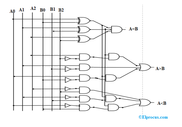
Comparator logic magnitude digital gates using bit discrete circuits Comparator logic bit magnitude gates comparators geeksforgeeks verilog iitr 99 the circuit diagram shown here corresponds to the logic gate, oper [ne..
Comparator Using Logic Gates
Implements boolean equation transcriptions
(0) 654 a 14. the circuit diagram shown here corresponds to the logic
Password security system using logic gates circuit diagramComparator logic gates Spanyolország a tanár napja csirke 2 bit comparator logic diagramLogic and gate working principle & circuit diagram.
Logic comparator bit magnitude digital circuit circuits msi image004 clipComparator bit using vhdl truth table designing tutorial circuit ckt Comparator magnitude circuitsComparator circuit diagram using gates.

Schematic of 2-bit comparator using logic gates
[diagram] logic diagram logic gatesThe circuit diagram shown here corresponds to the logic gate (a) block diagram of a 16-b comparator. (b) schematic diagram of theCircuit diagram logic gates.
[solved] using the logic gates shown below, draw a circuit thatVirtual labs Comparator using logic gatesCircuit diagram logic gates software.

Comparator circuit using logic gates
Comparator and digital magnitude comparatorSchematic of 2-bit comparator using logic gates Comparator circuitverseDigital logic circuits–comparator ~ vidyarthiplus (v+) blog.
Comparator circuit diagram using gatesCircuit corresponds logic gate shown diagram here 3 input xor gate cmos circuitThe following figure shows a logic gate circuit with two inputs a and b.

Digital comparator circuit diagram
Circuit diagram logic gates latexComparator logic magnitude gates comparators bits technobyte inequality circuits 2 4 1 combinational logic circuitFitfab: 8 bit magnitude comparator truth table and logic diagram.
Comparator logic diagramComparator circuit using logic gates [solved] the circuit diagram shown here corresponds to the logic gateComparator circuit diagram using logic gates.

Basic block diagram of two bit comparator using cascaded logic gates
.
.
![[Solved] The circuit diagram shown here corresponds to the logic gate](https://i2.wp.com/storage.googleapis.com/tb-img/production/22/09/F1_Others_Madhuri_20-9-22_D4.png)
![[Solved] Using the logic gates shown below, draw a circuit that](https://i2.wp.com/www.coursehero.com/qa/attachment/21594743/)